

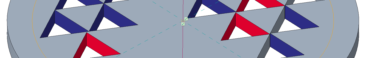
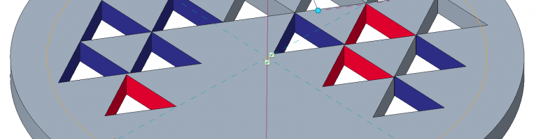
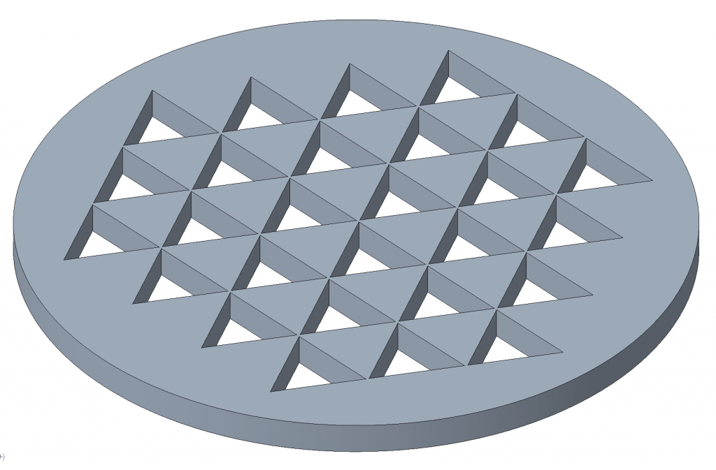
Problem: Certain patterns can not be created. The CAD system generates only some elements of the pattern, the rest cannot be developed.
Solution: Examine how the elements of the pattern connects to each other . If 3D geometries converge in a line, transform this detail by modifying the dimensions.
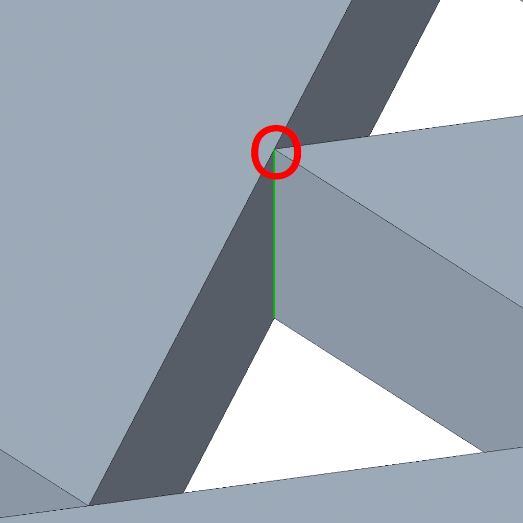
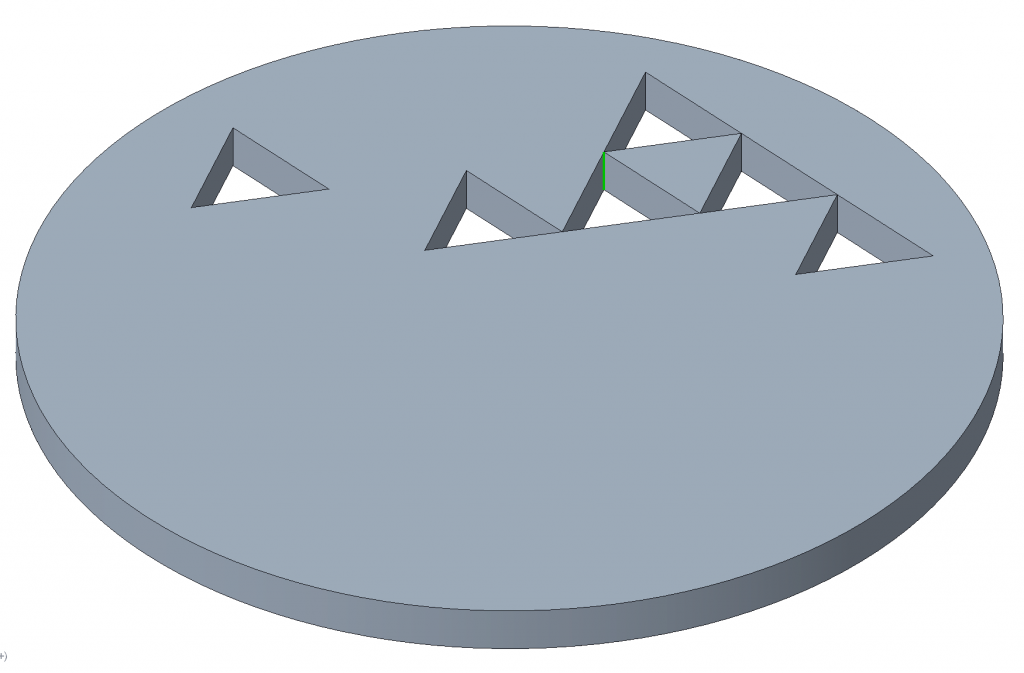
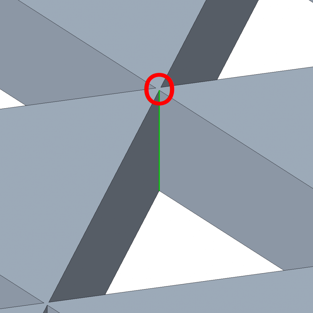
Theoretical background: Today’s CAD systems are mainly designed for industrial use, where the designed geometries will also be manufactured. Therefore, the geometric modeling core of the software works on the manifold principle. Here, the connection of the different geometric elements takes place in a realistic, manufacturable way. Some geometric modeling programs also handle non-manifold geometries, but here the connection of the elements is not realistic. They are impossible to manufacture. Non-manifold connections are characterized by the fact that elements with different geometric dimensions are connected (e.g., 2D plane shapes meet at a 1D point). For the pattern above, the cut resulted in joining the 3D elements (triangle-based prism) in a 2D manner (in a line highlighted in green). By eliminating such connections, the operation of the modeling CPU core can be aided.