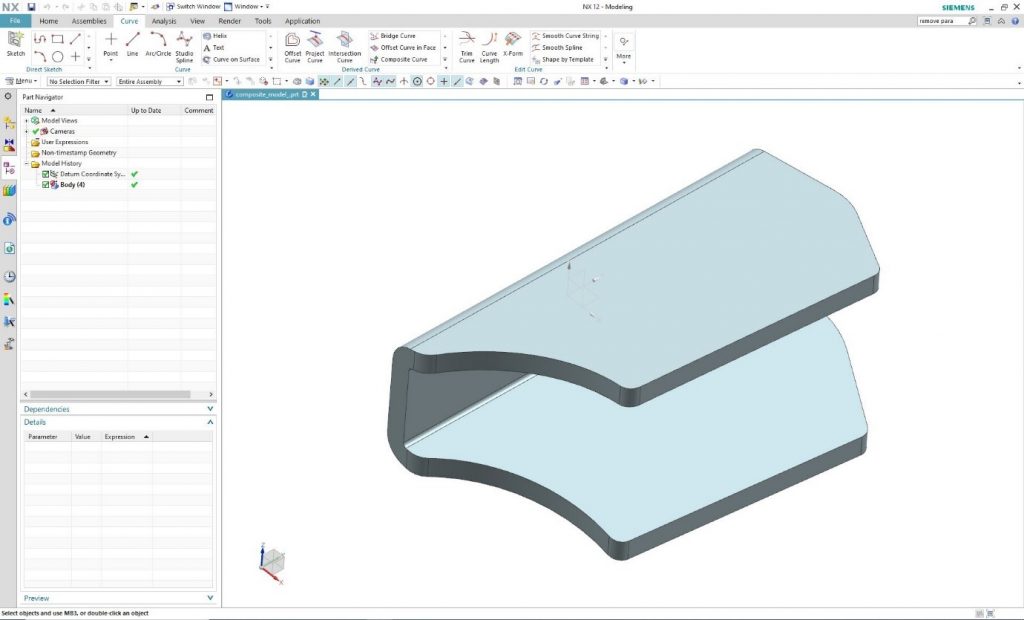
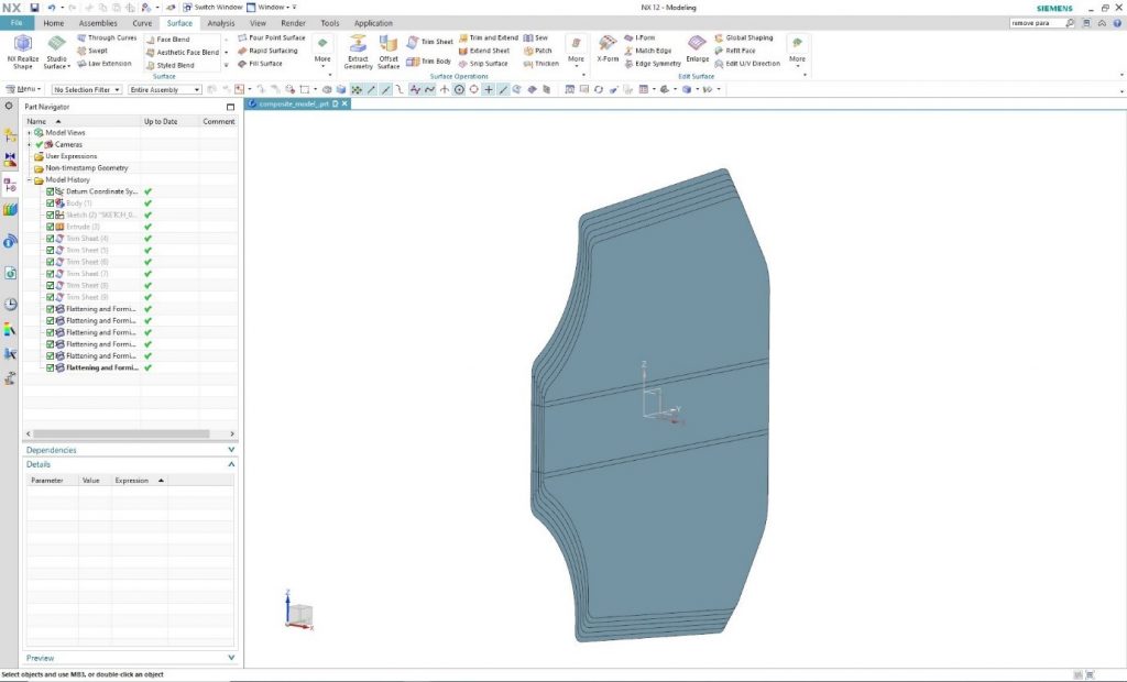
The goal is to create a flattening view of the following component mesh in Siemens NX system.
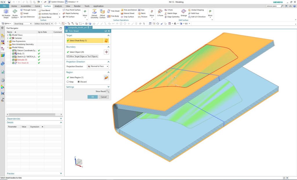
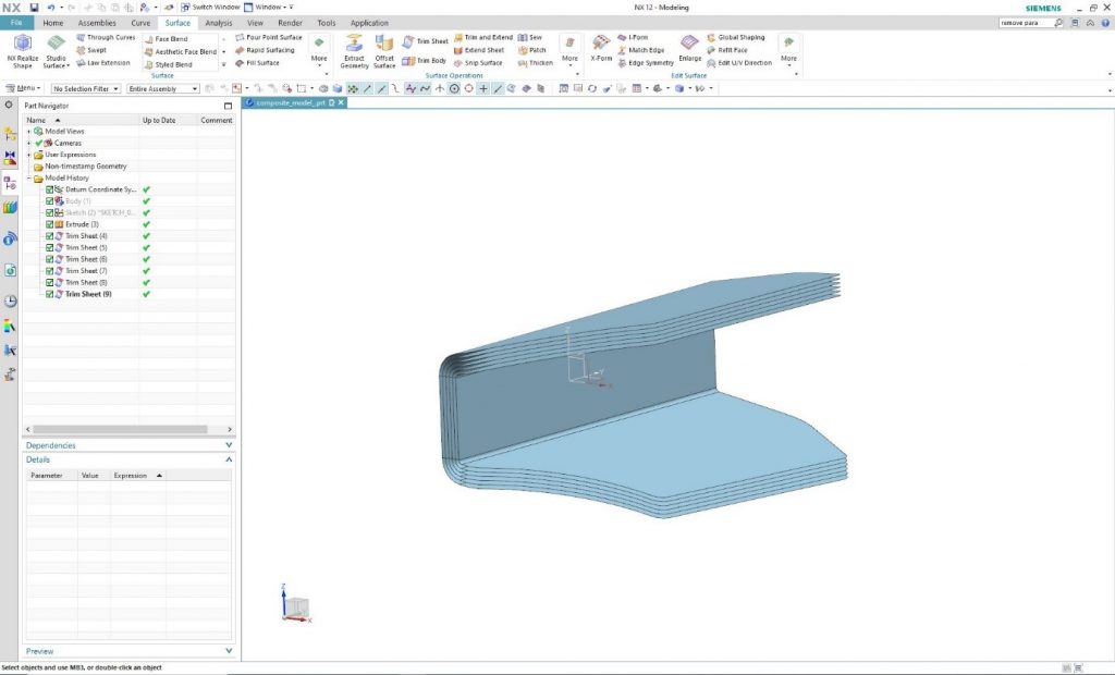
Define planes in the cross-sections where the size-determination of the mesh is necessary. Then, with the help of the “Trim Sheet” command, it is possible to cut the planes that results exactly the given cross-sections.
By hiding the original component its 6 cross-sections become visible.
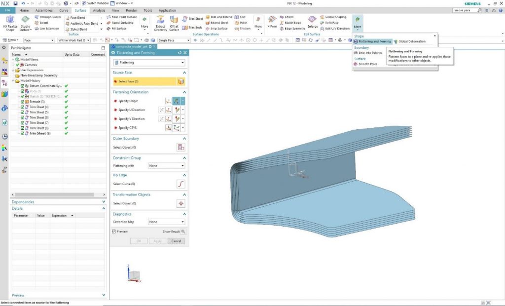
These surfaces can be flattened by using the “Flattening and Forming” command. In this way, the shape, size of the cross-sections and exact cut pattern of the mesh is provided. Run the command and in the “Source Face” it is needed to select the interface to be flattened.
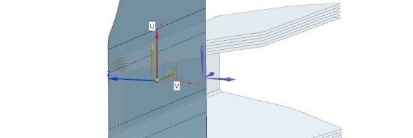
Specifying the coordinate system in which the program will spread the surface is possible under the “Flattening Orientation” tab. By clicking on one of the selected surfaces, the program automatically generates the coordinate system, the required origin, and the U and V direction. Of course, it is possible to deviate from this by individually defining components.
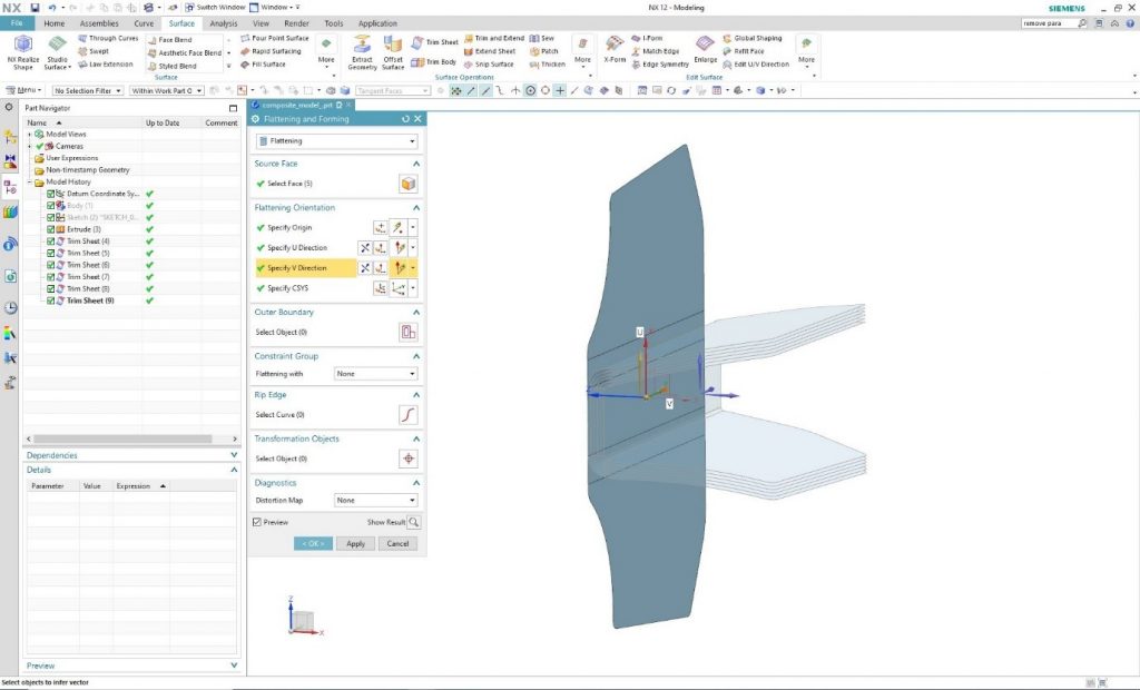
As the orientation is determined, and “Preview” is enabled, the program will flatten the surface. Based on the previous step, the process should be repeated on the other surfaces one by one.
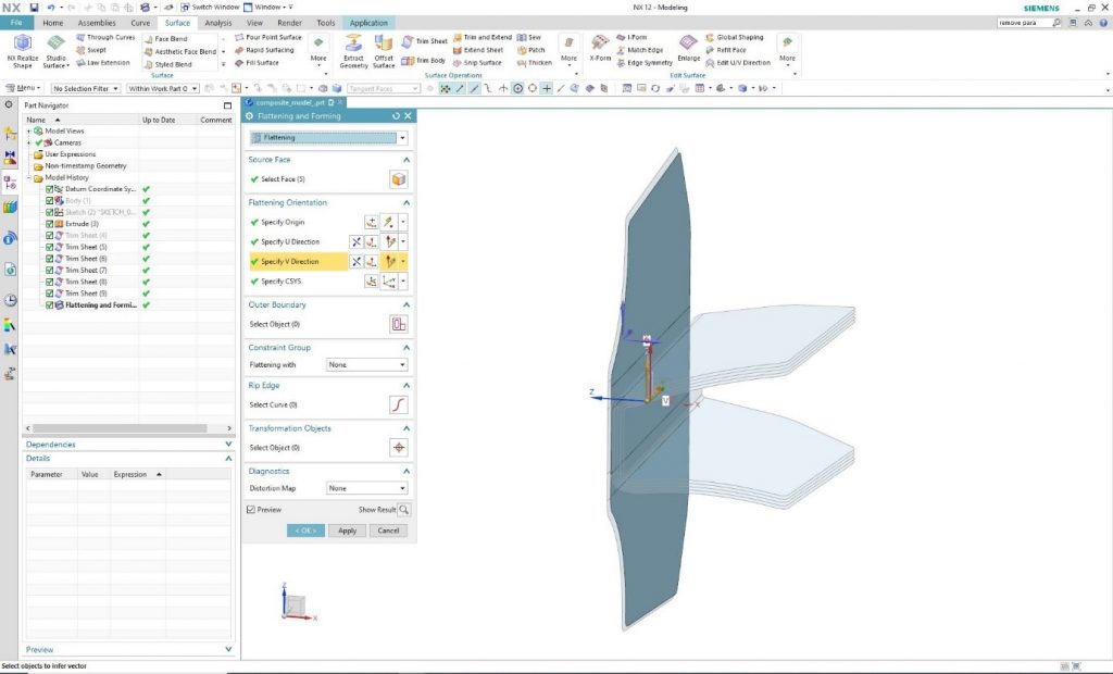
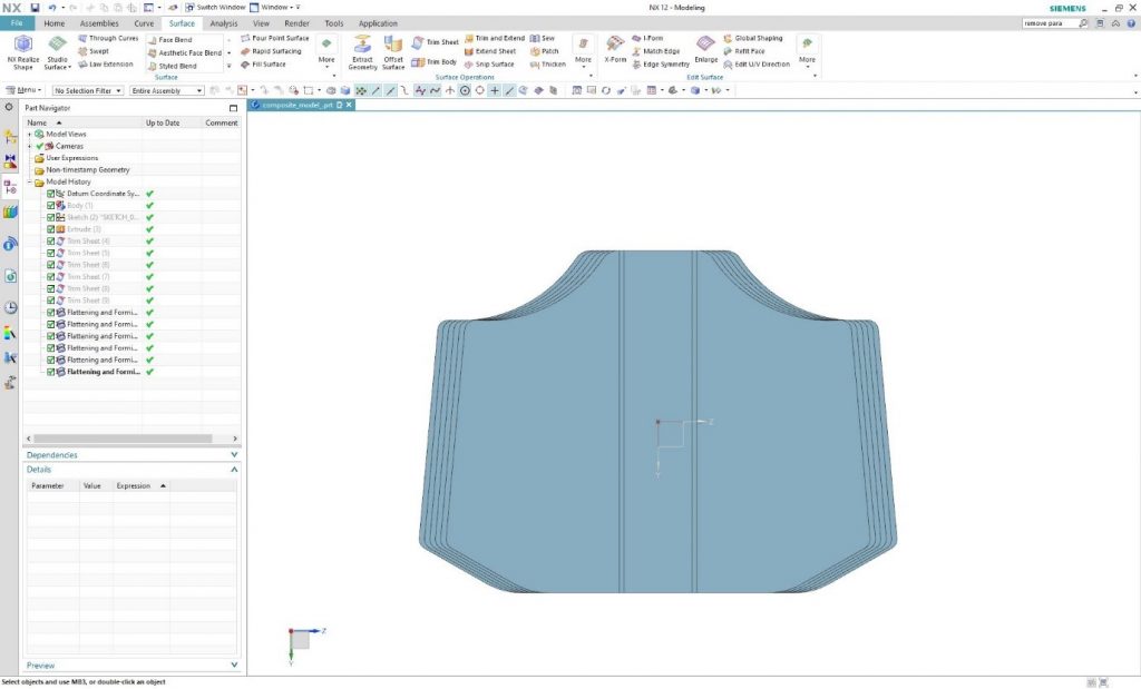
By finishing the flattening processes and hiding the original surfaces, only the unfolded cross-section remains visible.
From the front view, the necessity of the smaller or larger modification of surfaces can be determined by evaluating the shape of different cross-sections.
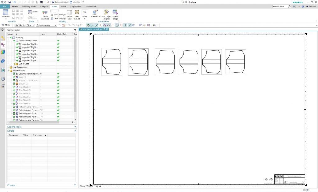
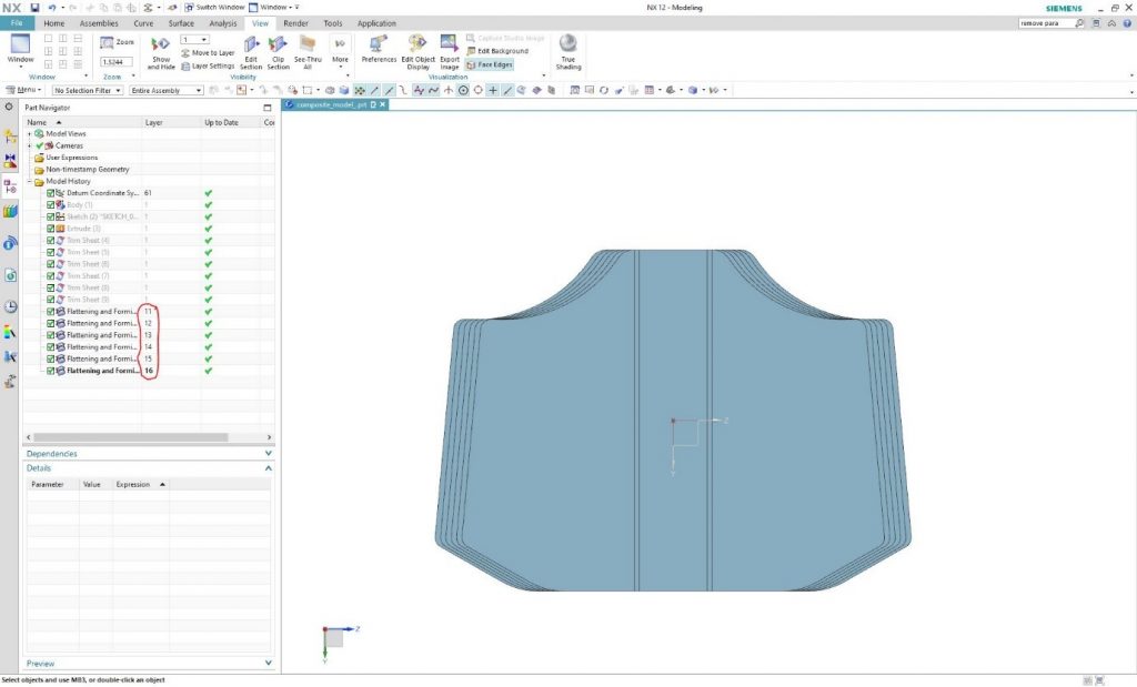
Should the mesh surfaces be required to be placed on a drawing beside each other (e.g. to export .dwg or .dxf files) the simplest way is to place them in different Layers. In this specific case, layers from 11 to 16 were used.
In the drawing module, the number of used views should match the number of displayed surfaces. In this specific case, it is 6.
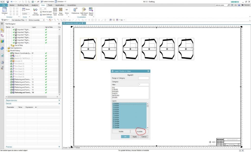
Then in the “View” tab, look for (the command finder may help) the “Layer Visible in View” command. With this command, it is possible to set the “Layer” or “Layers” in the views separately. Select the first view and the window in the next step will appear.
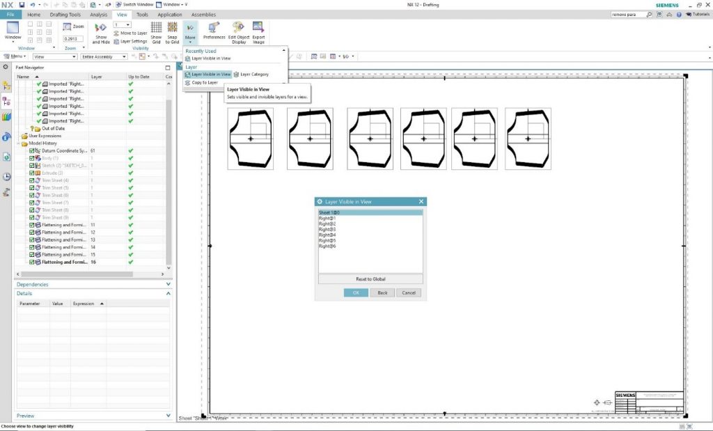
All 256 layers can be seen, and these layers could be set to remain “Visible” or become “Invisible”.
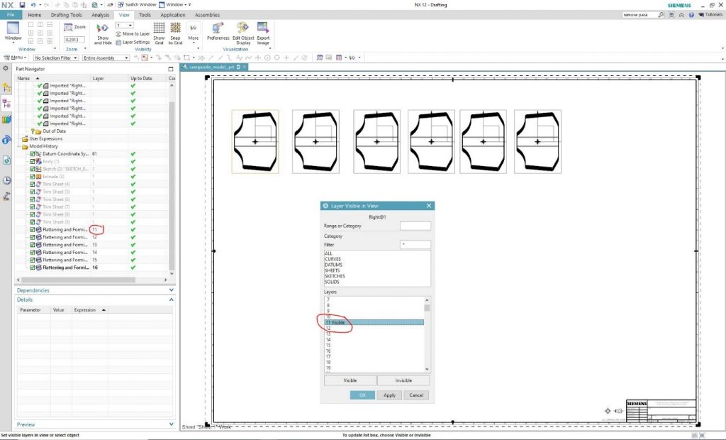
Set the first view to show only Layer 11, then click OK.
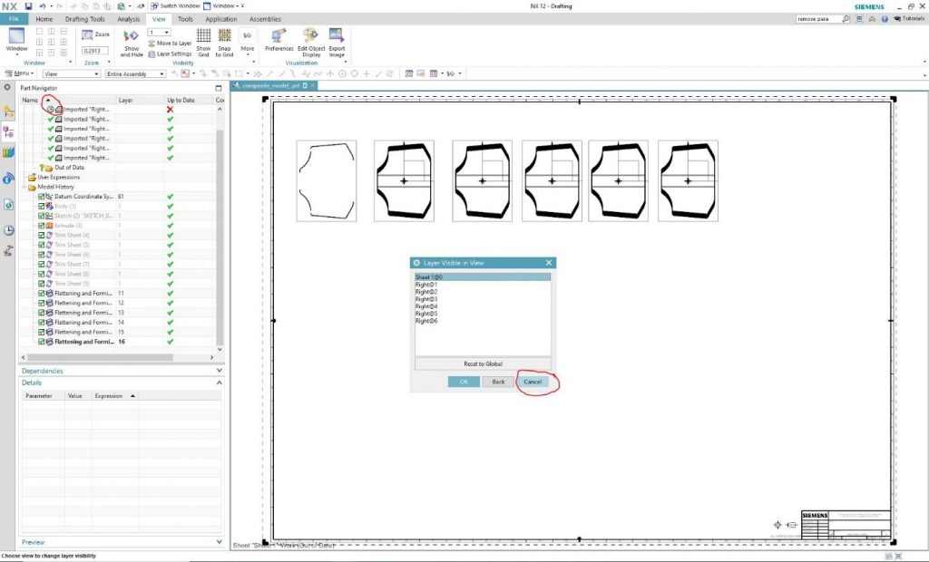
The program will lead us back to the view selection window. It is shown that the view needs an update. Use the “Cancel” command to close the window and then refresh the view.
Refresh the view so only the view connected to the selected layer is visible.
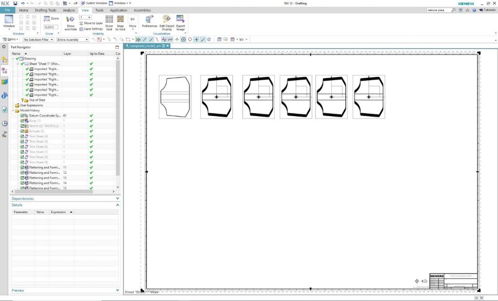
The process is repeated until only one layer is visible in each view and after that .dxf and .dwg files can be exported from the drawing.